
What Are Construction Drawings?
- Joseph W.

- Jul 12, 2021
- 4 min read
Updated: Aug 30, 2022
In short, Construction Drawings are essentially a complete set of instructions used during the construction of any new building or substantial renovation. These instructions are commonly found on 24"x36" or 30"x42" paper, and in modern times, created on a computer using specialized Architectural design software. Referred to by many different names such as; Blueprints, Plans, House Plans, Etc., Construction Drawings are used to communicate vast amounts of information to home owners, permitting departments, and contractors. The information found in a set of Construction Drawings should always lead to a good understanding of how a home will be arranged, what the home will look like when construction is complete, and most importantly, how to actually build it!

What's Typically Included in a Construction Drawing?
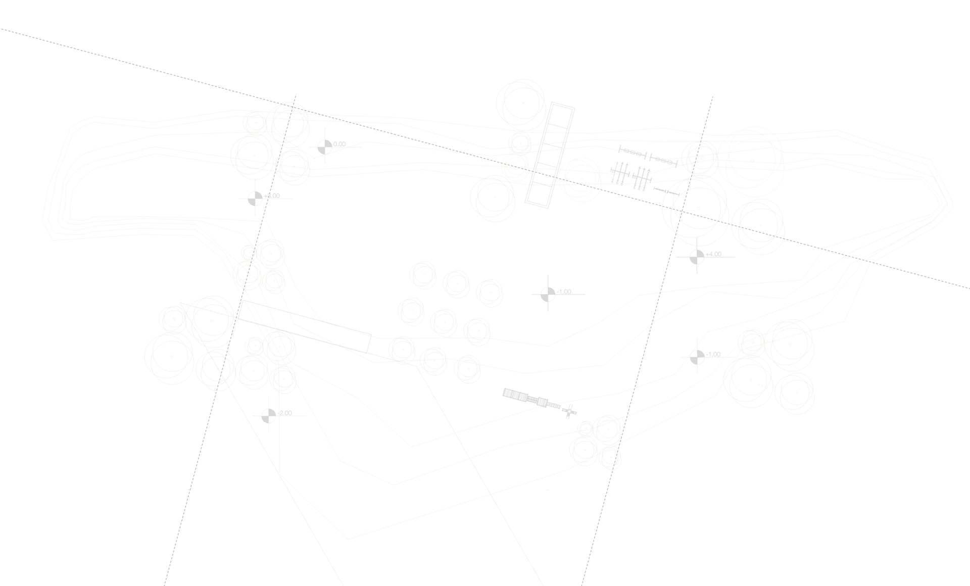
In a Construction Drawing, or set of Construction Drawings, you should expect to find most of the details you need to build any given home. These details are typically divided and organized throughout multiple sheets, each of which are particular to one or two building trades. These sheets are commonly identified with a Sheet Number and Sheet Title found in the title block, or somewhere on the perimeter of the sheet. As an example, you may open a set of Construction Drawings to sheet "E1.0 / Electrical" which you can expect to find information particular to, you guessed it, the Electrical systems! As far as what sheets and how many you might find in a set of Construction Drawings, this will vary depending on the location, size, and complexity of each home. So that you're not left entirely in the dark, we've included an example below from a 2,600 Sq. Ft. home built in California. Please keep in mind that not all Architects and/or Designers use this exact format, but this at least gives you a rough idea of how information in broken down in many cases.
Sheet Index
G0.1 - General Information
A1.1 - Plot Plan
A2.1 - Floor Plan
A3.1 - Exterior Elevations
A3.2 - Exterior Elevations
A4.1 - Interior Elevations
A5.1 - Building Cross Section
A6.1 - Architectural Details
E1.1 - Electrical Plan
P1.1 - Plumbing Plan
S1.1 - Foundation Plan
S2.1 - Shear Wall Plan
S3.1 - Roof Structure Plan
S4.1 - Structural Details
S4.2 - Structural Details
Now, it's important to note that not ALL details for construction are included in these Construction Drawings alone. In addition to these "Plans" or "Blueprints", often times permitting departments will require more intricate details to be provided in the form of "Supporting Documents". A few examples of these Supporting Documents are; Energy Evaluation Reports, Structural Calculations, Concrete Mix Design, Site Survey Details, etc. These Supporting Documents function as one with the Construction Drawings and are intended to provide further documentation of both code compliance and construction feasibility. As every property comes with their own unique complexities, it's always best to verify with your local permitting department as to which Supporting Documents will be required to accompany your Construction Drawings.

Common Sheets & Details
G0.1 - General Information
- Project Title
- Project Location
- Vicinity Map
- Construction Type
- Occupancy Type
- Applicable Codes
- Design Criteria
- Typical Notes & Disclaimers
A1.1 - Plot Plan
- Property Specific Information
- Proposed Location of Home
- Building Setbacks
- Easements
- Property Constraints (Hills, Cliffs, Retaining Walls)
- Site Utilities
- Driveways
- Landscaping
- Hardscaping
A2.1 - Floor Plan
- Dimensions
- Walls
- Doors
- Windows
- Room Descriptions
- Ceiling Heights
- Appliances
- Plumbing Fixtures
- Fireplaces
A3.1 - Exterior Elevations
- Exterior Finish Materials
- Door & Window Heights
- Roof Pitches
- Floor Heights
- Plate Heights
- Roof Peak Heights
A4.1 - Interior Elevations
- Interior Finish Materials
- Cabinetry
- Appliances
- Shelving
- Lighting
- Ceiling Projections
A5.1 - Building Cross Section
- Cut Throughout Building
- Roof Assembly
- Roof Structure
- Insulation Values
- Wall Assembly
- Room Descriptions
- Foundation Assembly
- Footings
A6.1 - Architectural Details
- Door Thresholds
- Head Conditions
- Sill Conditions
- Flashing Details
- Roof Assembly
- Eave Assembly
- Exterior Finish Assembly
- Other Unique Terminations/Conditions
E1.1 - Electrical Plan
- Electrical Panels
- Outlets / Receptacles
- Lighting & Switches
- Fans & Switches
- Conduit
- Life Safety
- Data / Internet Drops
- Security & Cameras
- Cable
P1.1 - Plumbing Plan
- Incoming Water
- Incoming Gas
- Hot & Cold Water Routes
- Gas Routes
- Plumbing Fixtures, Appliance, & Stubs
- Gas Fixtures, Appliances, & Stubs
S1.1 - Foundation Plan
- Foundation of Type
- Dimensions
- Rebar / Reinforcement Requirements
- Footing Sizes & Locations
- Anchors, Post Bases, and Hold Downs
- Vapor Barrier
- Floor Framing
S2.1 - Shear Wall Plan
- Shear Wall Locations
- Shear Wall Schedule
- Shear Wall Assembly
S3.1 - Roof Structure Plan
- Manufactured Roof Trusses
- Headers & Beams
- Rafters
- Ridge Beams
- Post Caps
- Straps & Clips
S4.1 - Structural Details
- Footing Assemblies
- Shear Wall Assemblies
- Framing Conditions
- Connector Conditions
- Strapping & Anchorage Details
We hope to hear that this article has been of value to you! Please feel free to contact our team with any questions or concerns regarding this article. Click here to redirect to our contact page, or feel free to explore related content here.
Photo Credits; https://unsplash.com/
#Education #ConstructionDrawings #Houseplans #Blueprints #Plans #TechnicalDrawings #ConstructionPlans #Structural #Electrical #California #Compliance #Permit #Construction #Architecture #Engineering #Builders #Contractors #Homeowners Architect Redding Ca, Drafter Redding Ca, Home Builder Redding Ca, Luxury Home Builder Redding Ca


Comments